|
Illustrate Actor-Use Case interactions using Use Case Diagrams |

|

|

|
|
|
Illustrate Actor-Use Case interactions using Use Case Diagrams |
|
|
|
Illustrate Actor-Use Case interactions using Use Case Diagrams
|
Illustrate Actor-Use Case interactions using Use Case Diagrams |
|
|
|
|
|
Illustrate Actor-Use Case interactions using Use Case Diagrams |
|
|
|
Overview
Use Case Diagrams can be effectively used to communicate the high level functionality of the system to the stakeholders in a concise and easy-to-understand visual format.
Use Case Diagrams show how Actors interact (or communicate) with the system via Use Cases; they also also show how the Use Cases interact with each other. i.e. <<include>> and <<extend>> relationships between Use Cases.
Using TopTeam, you can represent the system under development using one or more Use Case Diagrams, with each diagram focusing on a different functional area of the system.
To draw a Use Case Diagram, follow these steps:
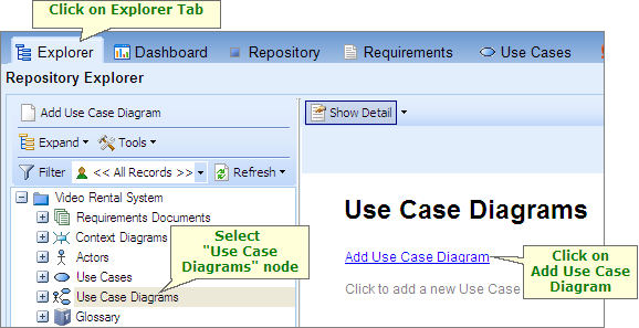
Open Repository Explorer and click on the Use Case Diagrams header node. Click on Add Use Case Diagram.
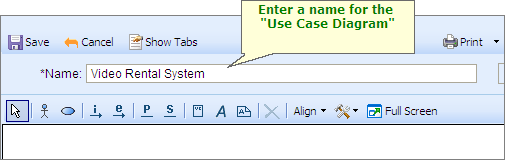
Enter a Name for the Use Case Diagram.
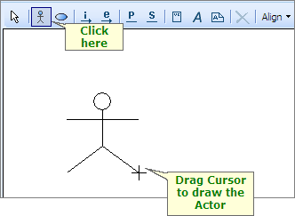
Draw Actors on the Use Case Diagram
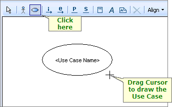
Click on the Actor icon on the toolbar and then drag the cursor on the diagram to draw an Actor shape.
The application displays a window that lists all existing Actors in the Repository. You can choose an existing Actor from this list or you can create a new Actor.
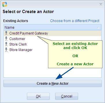
When you click on "Create a New Actor", the editor expands and allows you to enter the name and description for the new Actor.
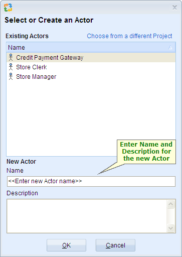
Click OK to place the Actor on the diagram.
NOTE
|
When you add an Actor or Use Case shape to the Use Case Diagram, the corresponding Actor and Use Case artifacts are automatically added to the repository.
When you remove an Actor or Use Case shape from the Use Case Diagram, the corresponding Actor and Use Case artifacts are NOT deleted from the repository. |
Draw Use Cases on the Use Case diagram.
Click on the Use Case icon on the toolbar and then drag the cursor on the diagram to draw a Use Case shape.
The application displays a window that lists all existing Use Cases in the Repository. You can choose an existing Use Case from this list or you can create a new Use Case.
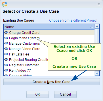
When you click on "Create a New Use Case", the editor expands and allows you to enter the name and description for the new Use Case.
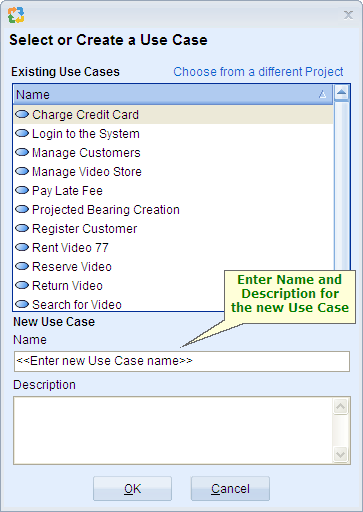
Click OK to place the Use Case on the diagram.
Create Primary and Supporting Actor relationships between Actors and Use Cases
NOTE
|
When you place existing Actors and Use Cases on the diagram, all Primary and Supporting Actor relationships between those Actors and Use Cases are automatically displayed on the diagram. You can also create new Primary and Supporting Actor relationships on the diagram. |
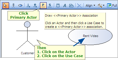
To create a Primary Actor relationship, follow these steps:
| • | Click on the Primary Actor relationship icon on the toolbar. |
| • | Click on the Actor shape. |
| • | Finally, click on the Use Case shape. |
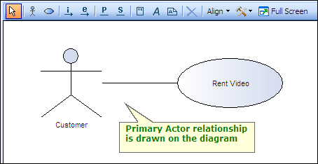
There NO need to drag the cursor on the drawing area in order to draw a line.
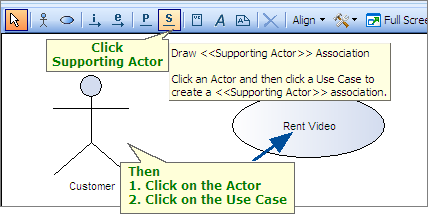
Similarly, you can create the Supporting Actor relationship by using the Supporting Actor icon on the toolbar.
IMPORTANT
|
When you draw a Primary or Supporting Actor relationship on the Use Case diagram, the corresponding relationship is automatically added to the repository.
When you delete a Primary or Supporting Actor relationship from the Use Case Diagram, the corresponding relationships is ALSO DELETED from the repository. |
Create include and extend relationships between Use Cases
NOTE
|
When you place existing Use Cases on the diagram, all existing include and extend relationships between those Use Cases are automatically drawn on the diagram. You can also create new include and extend relationships on the diagram. |
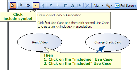
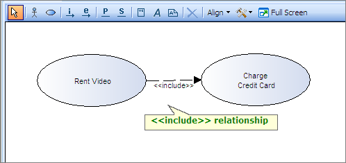
Use the <<include>> relationship to reuse a common functionality of the system in multiple places. For example, the scenarios for charging a credit card could be a common functionality required in multiple places in a system. You can create a Use Case called Charge Credit Card and then include it in other Use Cases wherever this functionality is required.
To create an <<include>> relationship between Use Cases, follow these steps:
| • | Click on the <<include>> icon on the toolbar. |
| • | Click on the first Use Case shape (the including Use Case). |
| • | Finally, click on the second Use Case shape (the included Use Case). |
There NO need to drag the cursor on the drawing area in order to draw a line.
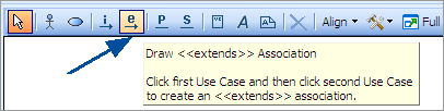
Similarly, you can create extend relationship between Use Cases by using the extend icon on the toolbar.
IMPORTANT
|
When you draw an include or extend relationship on the Use Case diagram, the corresponding relationship is automatically added to the repository.
When you delete an include or extend relationship from the Use Case Diagram, the corresponding relationships is ALSO DELETED from the repository. |
Finished Use Case Diagram
When you are finished, your Use Case Diagram will look similar to the sample below.

Sample Use Case Diagram
TIP
|
The Actor and Use Case shapes on the diagram are all linked to the corresponding artifact records in the repository. You can open the detail editor and edit their properties.
To open the corresponding detail editor to you can:
|
Step Complete
You have now successfully drawn a Use Case Diagram. You can proceed to create multiple Use Case Diagrams, each addressing a different functional area of your system.
Proceed to the next step.